Project 2 Generate Skin for Surface
Objective:
Use different method to generate skin, including
paneling tools and script. I will compare the two methods for future study.
Background:
In project 1 I made a surface of a building with
very fluent curves. Different skin will be an very attractive option for
project2.
Paneling
Tool Method:
Method1
1.
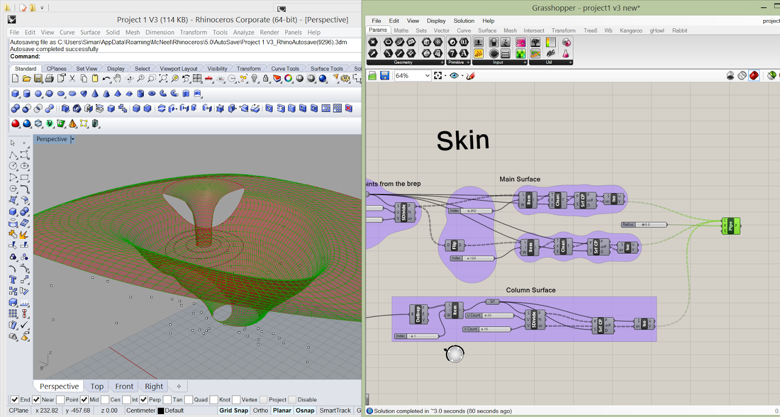
Use the surface created from Project1, which was
generated from “Loft”. Even if the surface had some trimmed area, the new skin
will ignore this “hole”. So I just use the untrimmed surface.


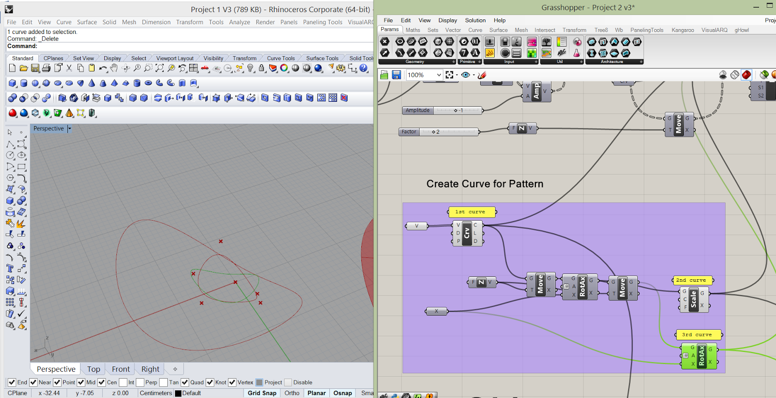
2.
Create several curves to prepare for future
module.
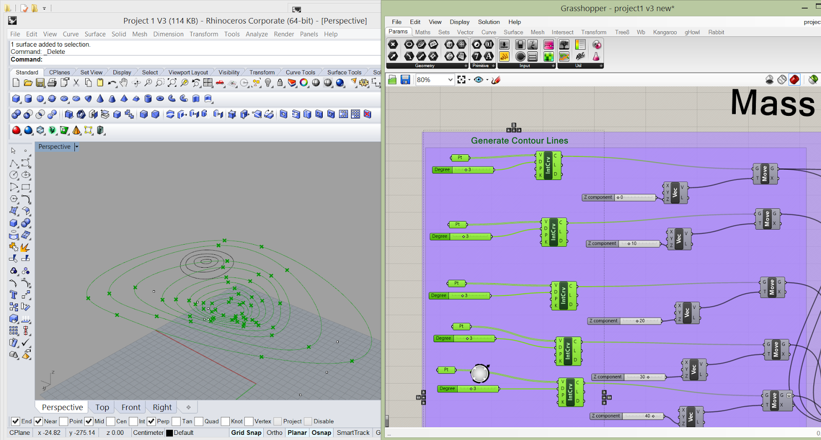
3.
Divide the surface into grids and make
coordinates.
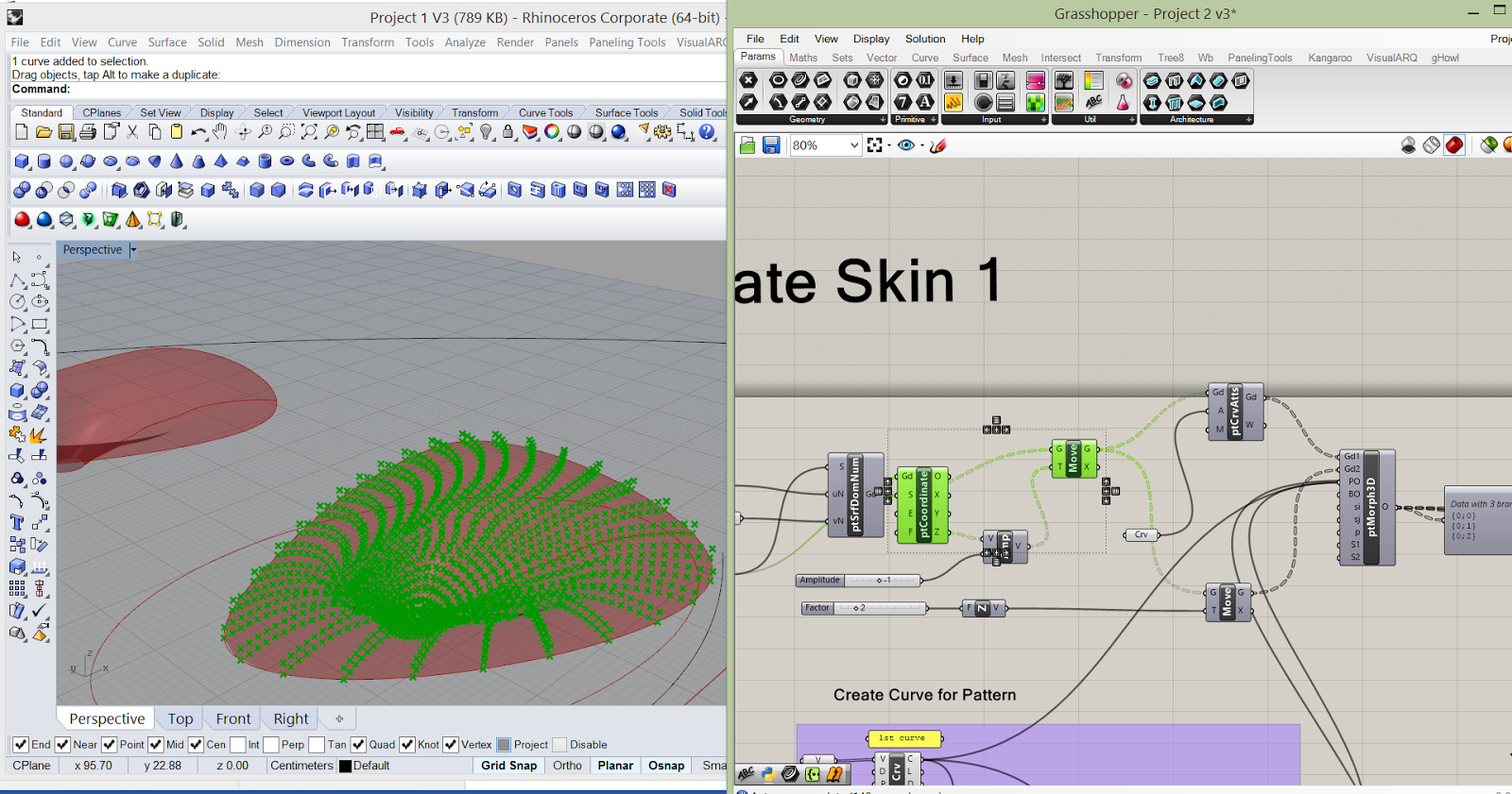

4.
Change the grid a little bit and use Morph3D to
morph curves onto the grid points.
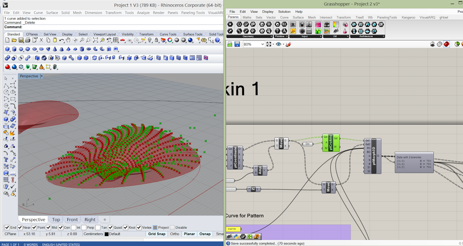
5.
Loft the curves and create the pattern.

Some
Tips:
1.
Use cull pattern to change the grid pattern

2.
Use Attractor to change the point location and
the pattern.

Method2
1.
Same as method1.
2.
Create several curves and loft them.

3.
Same as method 1.
4. Use
Morph3D to morph the loft surface onto the grid points.

Comparison between method 1 and method 2:
Method 2 is relatively easier.
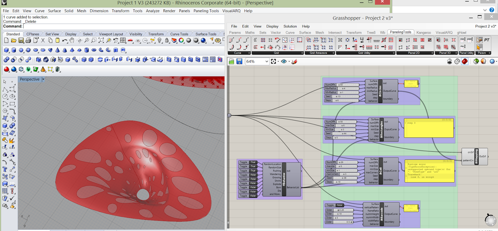
Script
Method:
1.
Get the source (from Chengde Wu)
2.
Adjust the volume of surface in case the
computation take too much time
3.
Adjust the data


Comparison:
Random
pattern:
The
script developed by Chengde Wu has the choice of random size and random
location, so the pattern can be changed easily. The paneling tools are confined
by the grid pattern that randomness of location and size might not be achieved.
But some other functions like GridAttractors can change the pattern on some
particular way.
Pattern
Shape:
The
script developed by Chengde Wu has some limits on the pattern module shape,
since it only had 4 choices. For paneling tool, the forms of module is various.
Basically as long as there is a grid pattern, you can attach any shape onto it.
The
script pattern is more like engraving patterns onto a material, while the
paneling tool is more like using small units and assemble them to a big system.
Stableness
and Time:
The script
method takes some time for computation, and it is easy to get stuck. The
paneling tool can be more smoothly during the process.
Video